


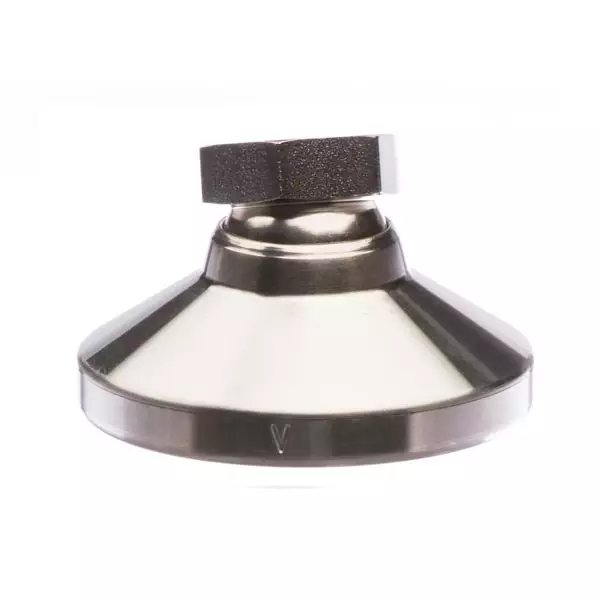
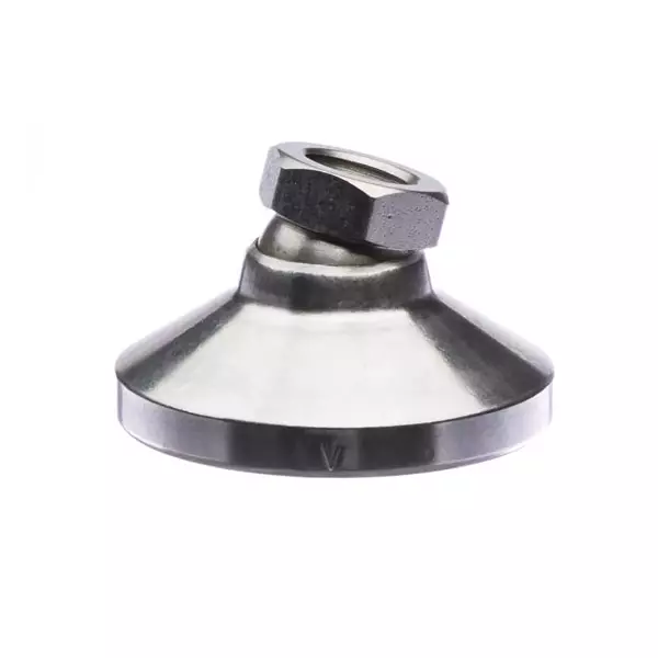
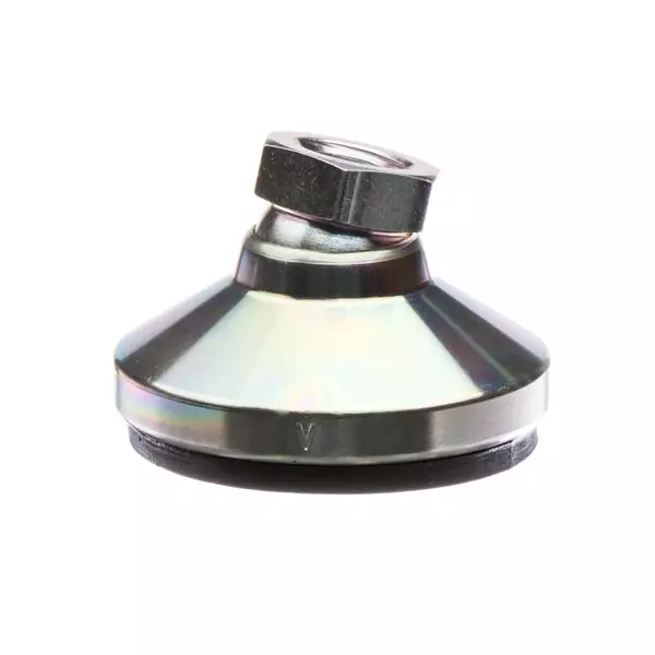
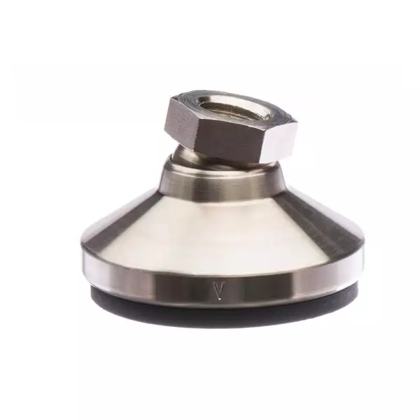

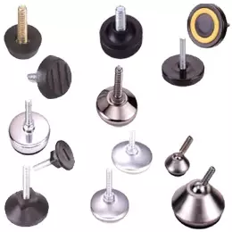


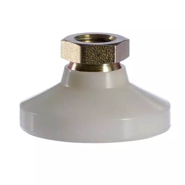
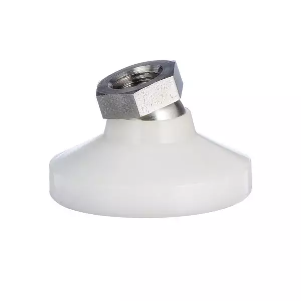


Spring Loaded Devices
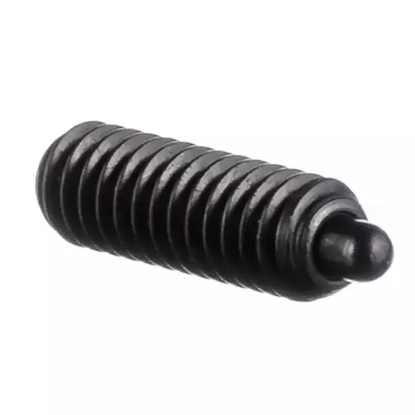
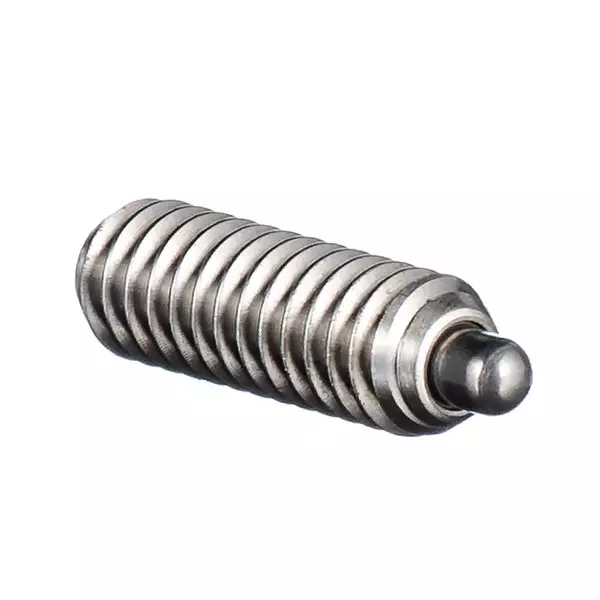
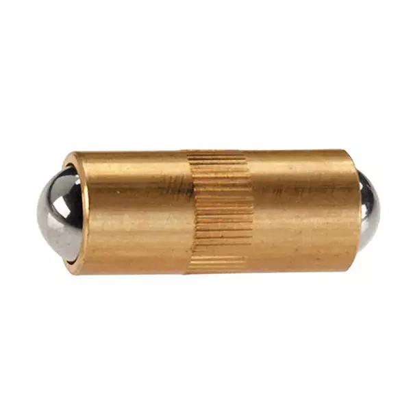
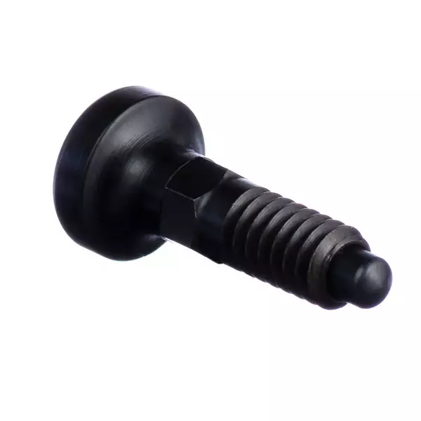
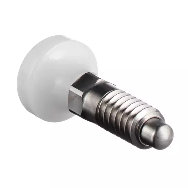
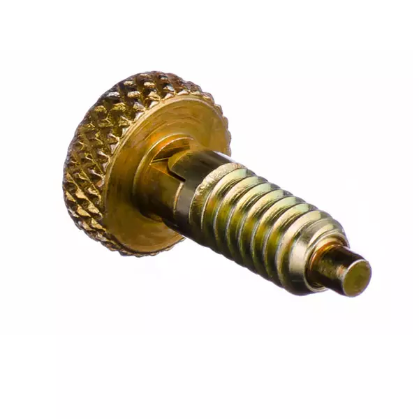
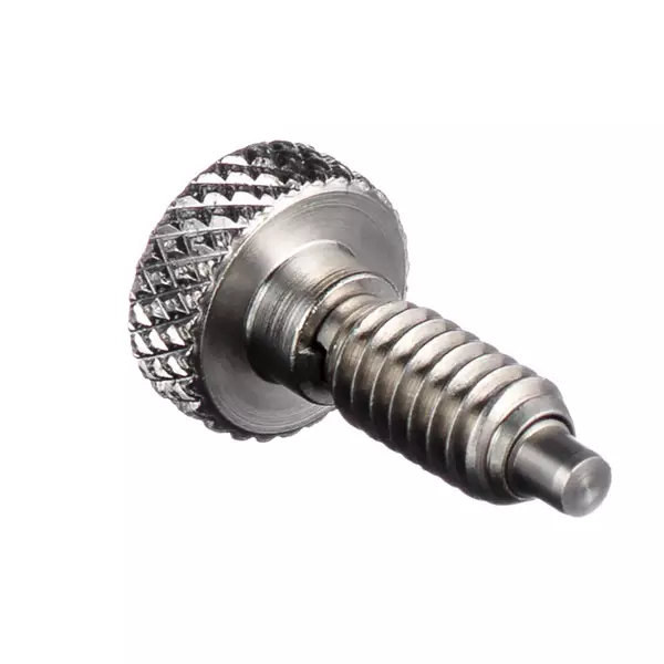
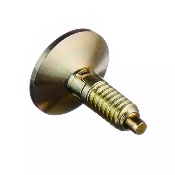
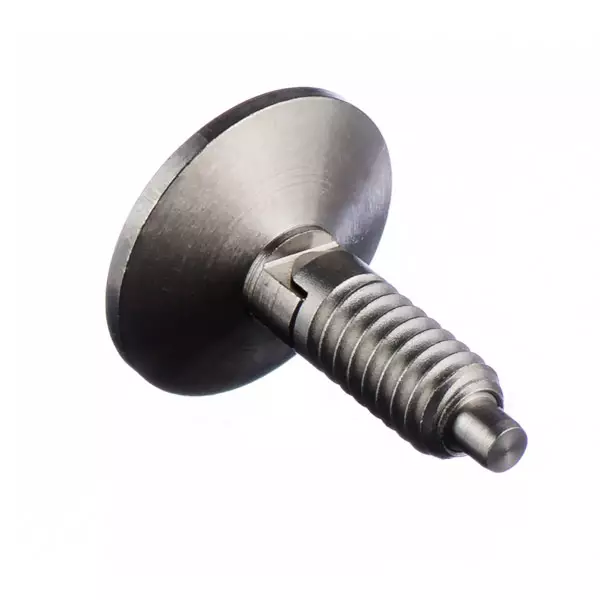
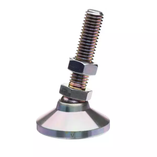
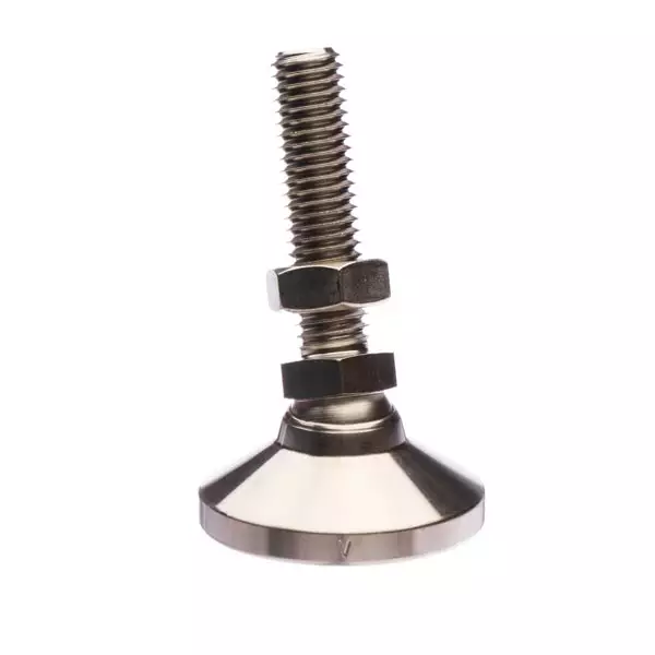
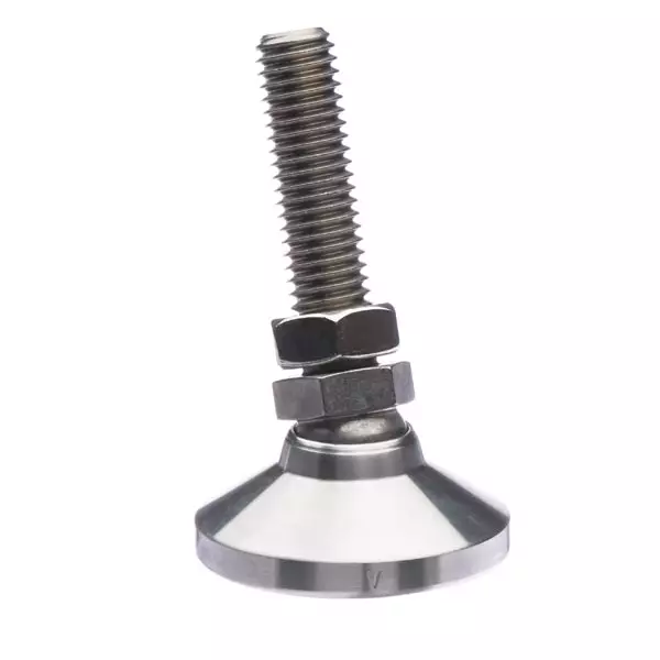
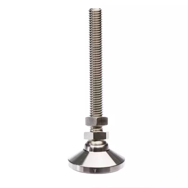
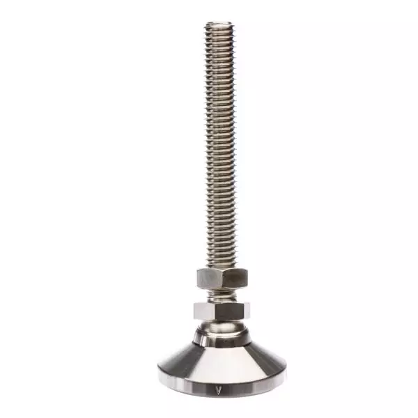
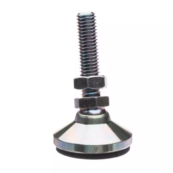
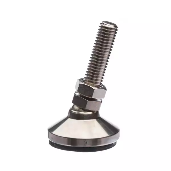
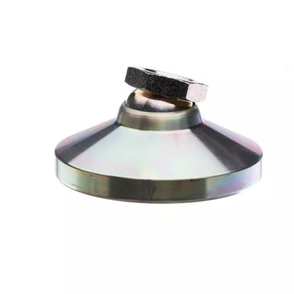
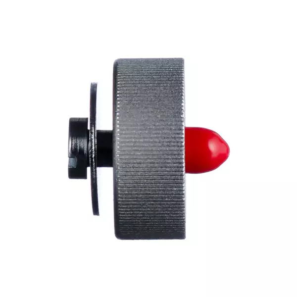
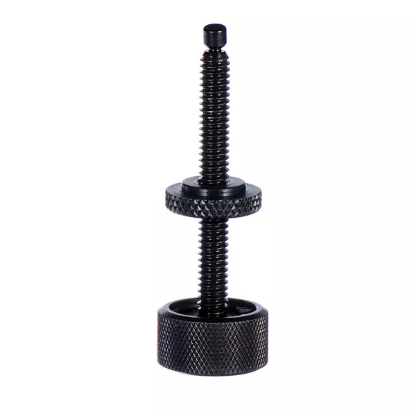
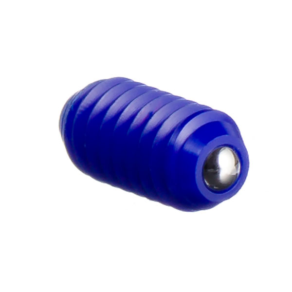
A spring-loaded device encapsulates a spring into its hollow body. With a plunger tip on one end, spring loaded devices allow for accurate and repeatable end forces.
Typical uses include: positioning, indexing, locating, ejecting, locking, latching, detents, contacts, lifters and insulators.
Choose from an array of spring plungers and spring devices in several design options and finishes, for jobs requiring accurate and reliable end forces or side loading.
Spring Loaded Devices (SLDs)
Learn more about Vlier’s spring loaded devices, including design details, available materials and common uses.
What is an SLD?
SLD Basics
Materials
With Thread Lock Elements
Detents/Hole Diameter
Installation
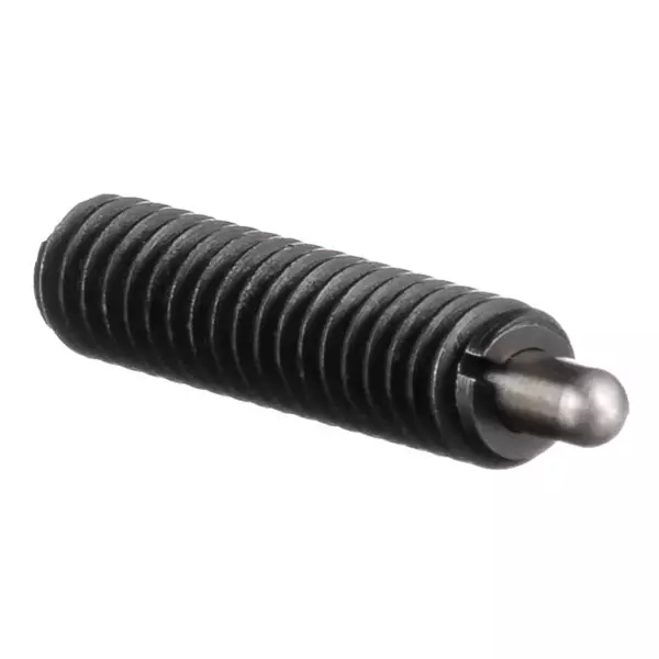
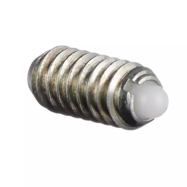
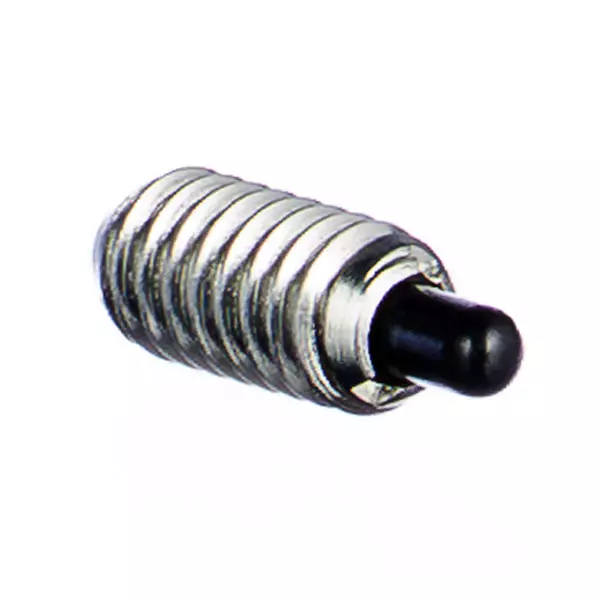
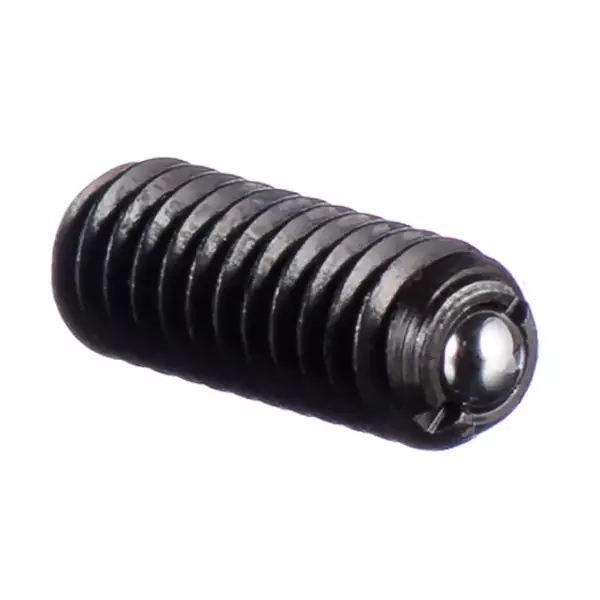
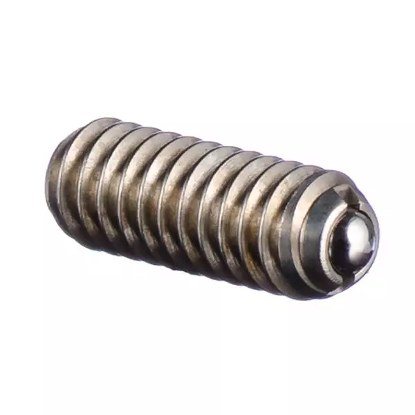
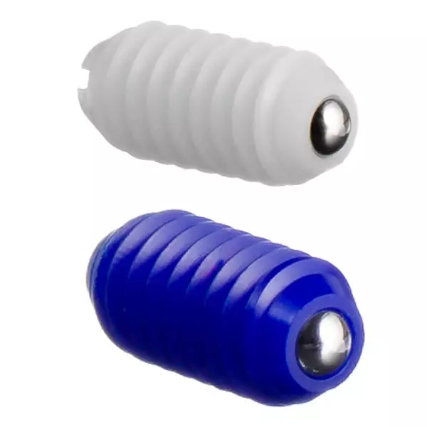
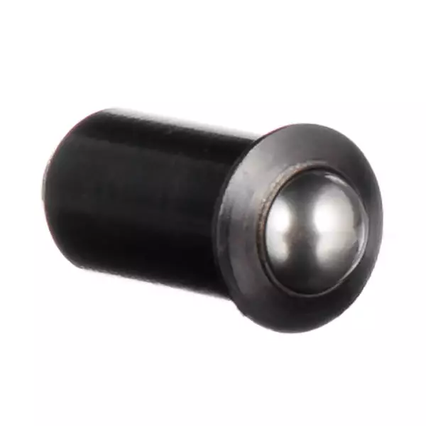
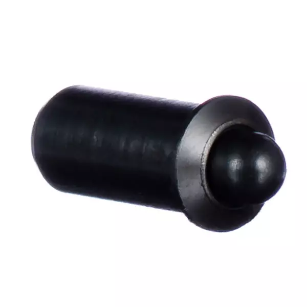
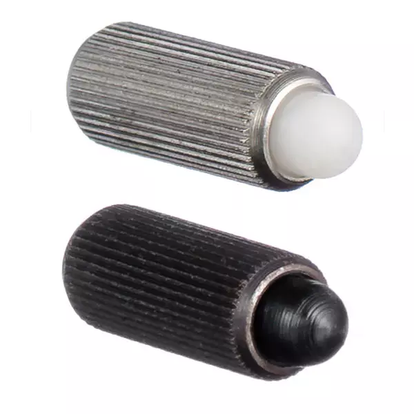
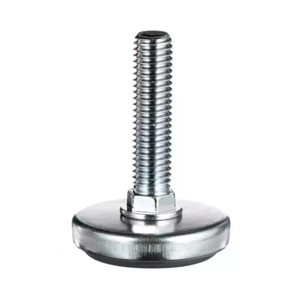
A spring loaded device (SLD), also called an enhanced spring, encapsulates a spring within its body, featuring a plunger tip or a ball on one end. This design adds value to the spring by enabling accurate and repeatable end forces.
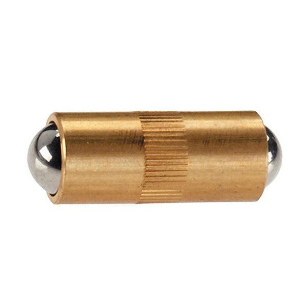
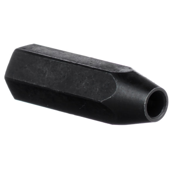
An SLD doesn’t have the head size of a screw or bolt and isn’t subjected to the same installation or fastening forces common with those parts. An SLD features a (hollow) threaded or push-fit style body that encapsulates the spring.
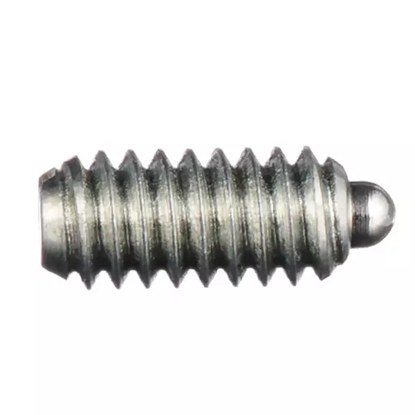
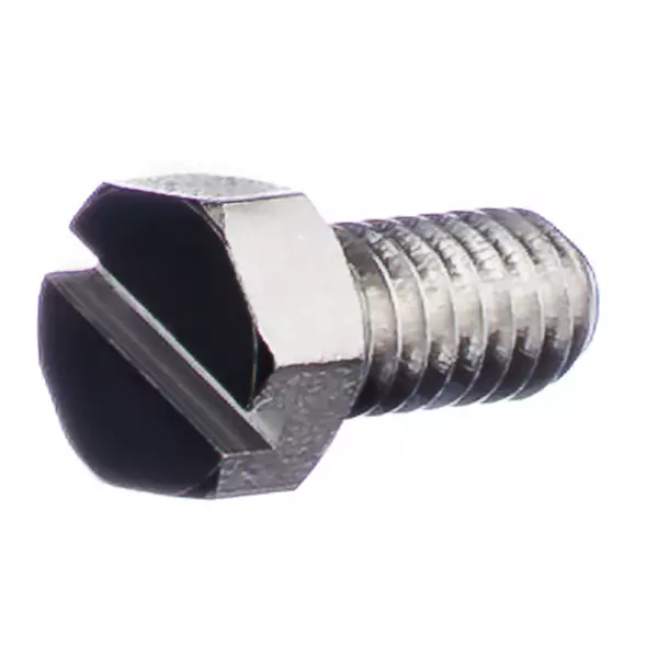
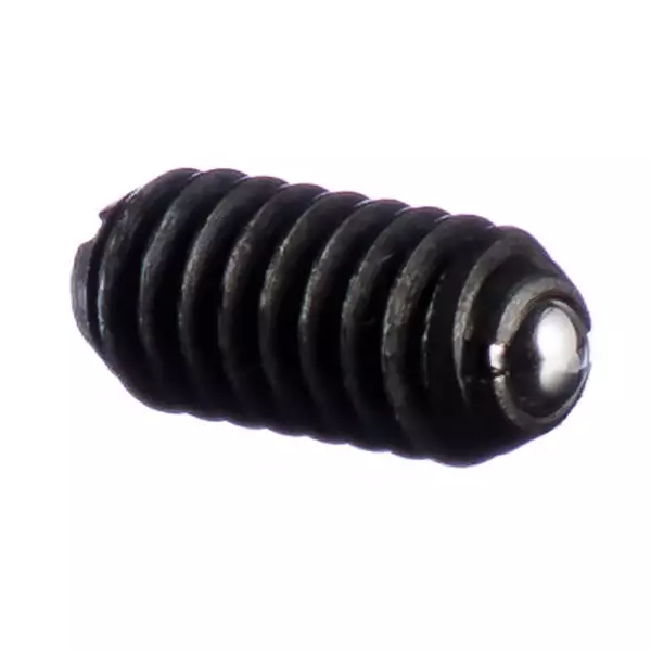
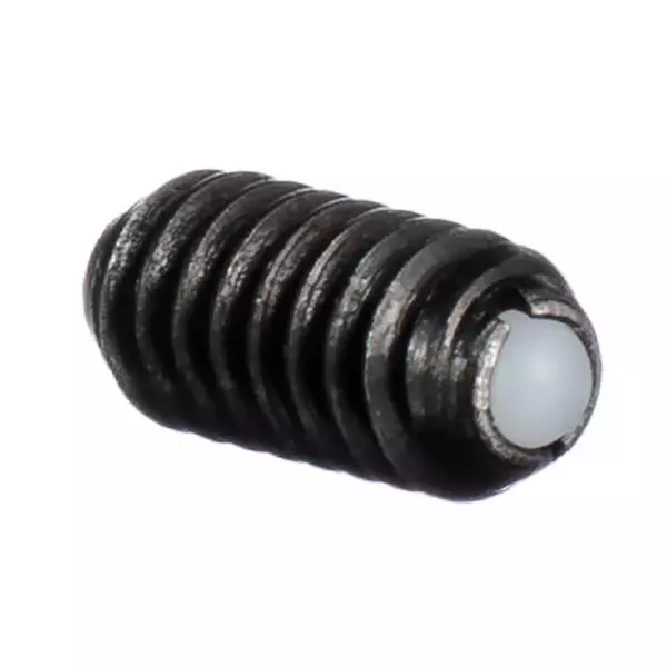
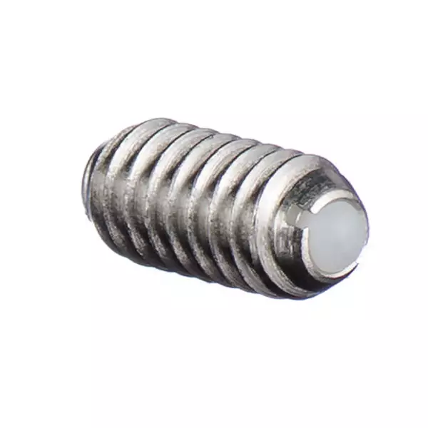
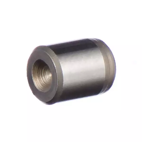
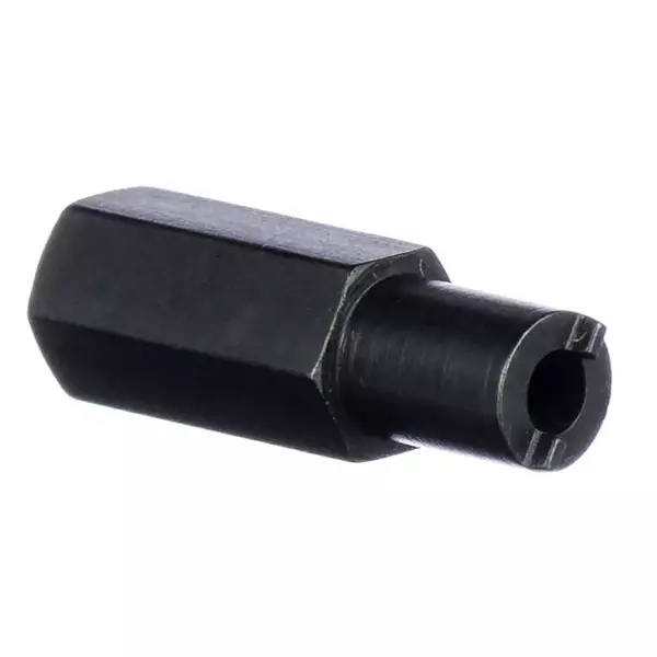
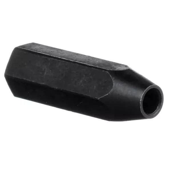
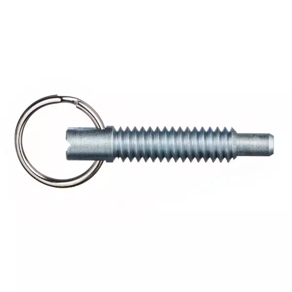
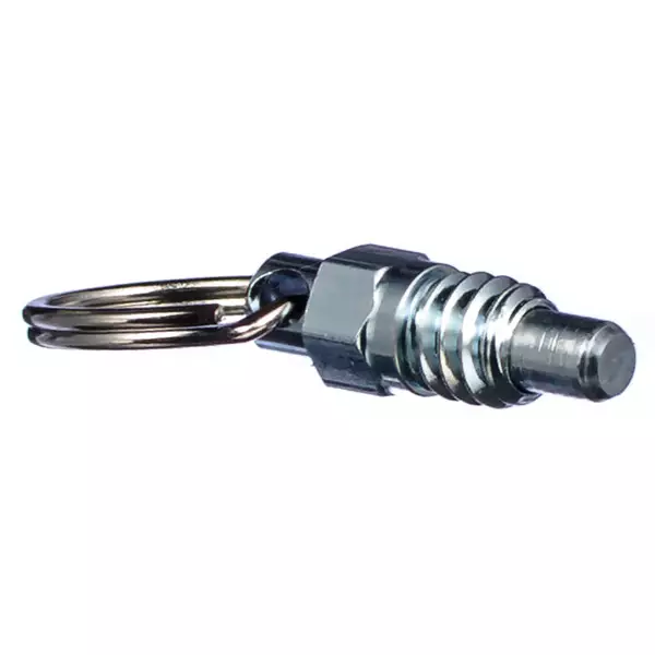
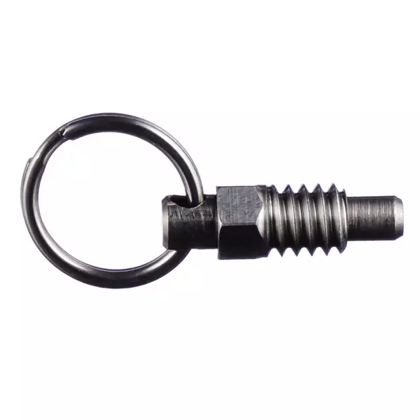
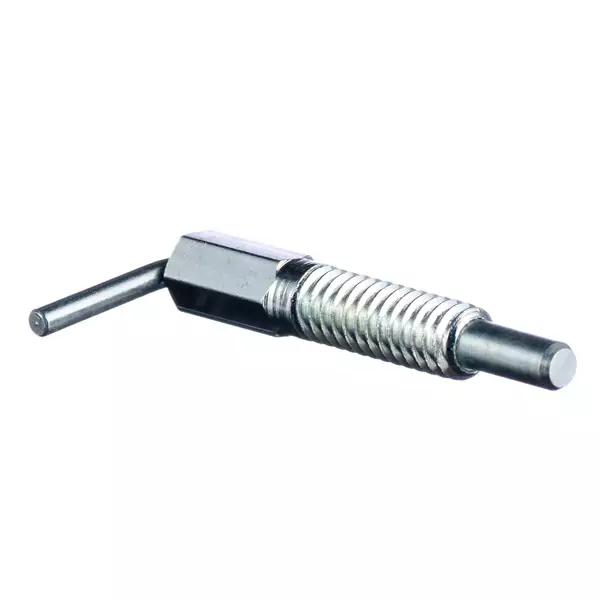
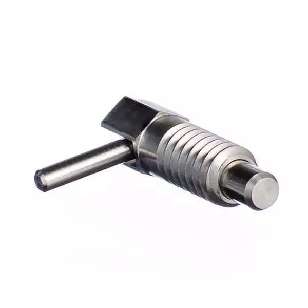
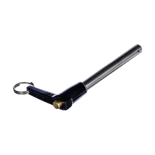
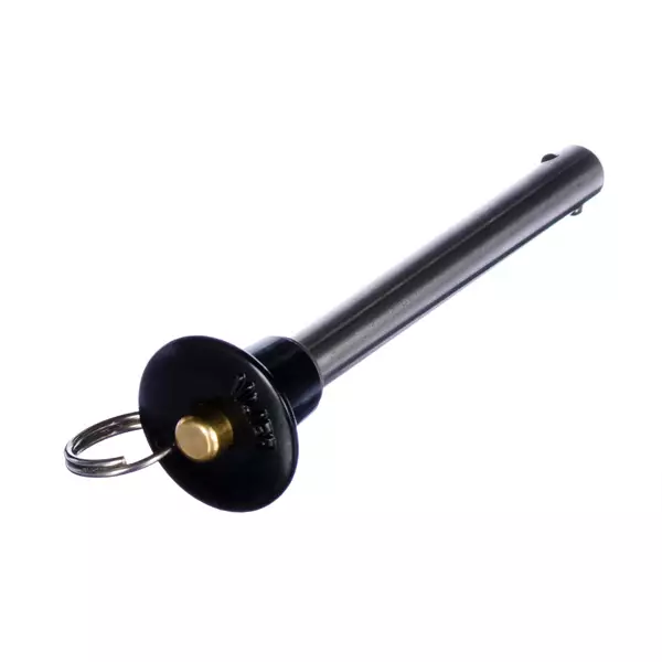
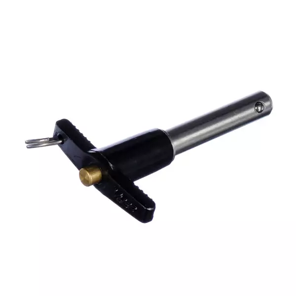
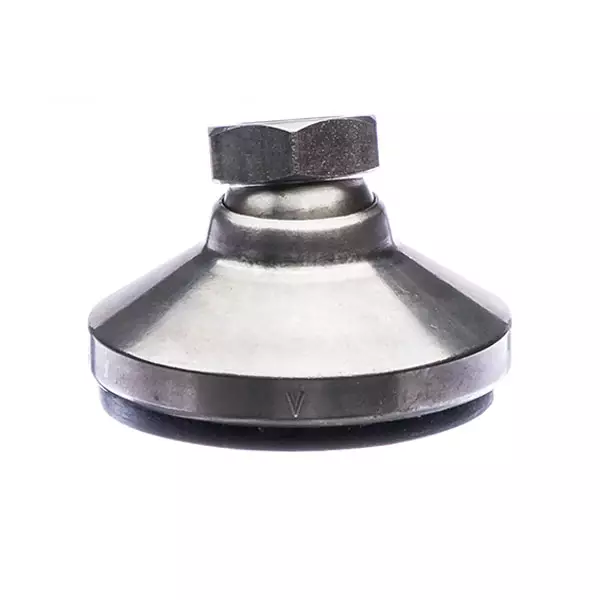
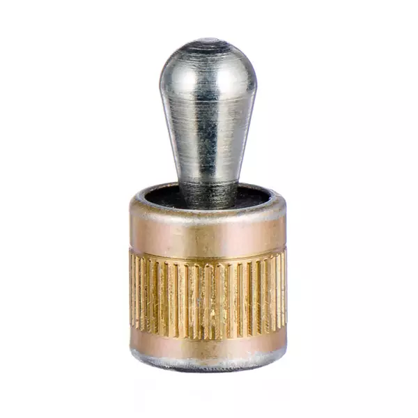
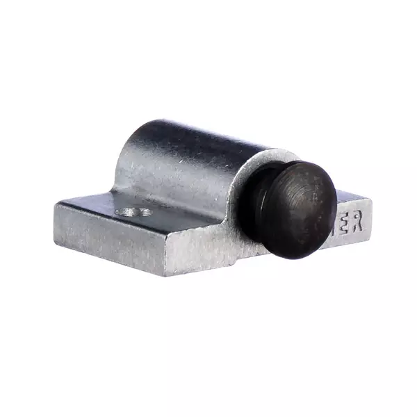
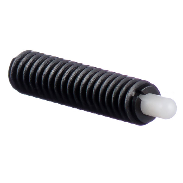
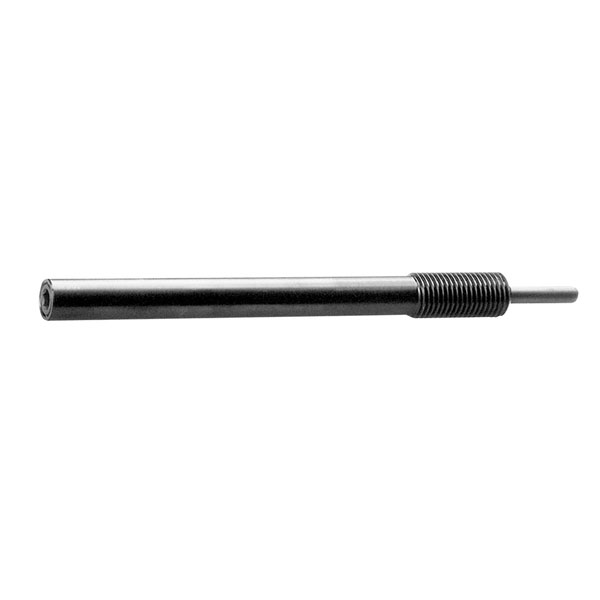
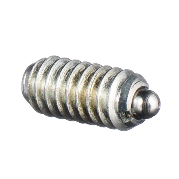
Vlier spring-loaded devices fall into four categories: standard spring plungers, stubby spring plungers, ball plungers and quick release plungers.
Reasons to Use an SLD
Common reasons for choosing an SLD over standard springs and self-manufactured parts include:
- Repeatable and accurate end forces
- Easier side loading, which standard springs can’t handle
- Easier installation than with standard springs
- Single assembly replaces multiple components
- Dependable and repeatable projection
- Minimal spring compression set
Before designing any SLDs into your product or application, Vlier recommends you read the SLD installation section.
End Force
Vlier Spring Loaded Devices (SLDs) exert a precise end force—ranging from 0.125 to 200 lbs.—dependably and accurately. Standard SLDs are offered in light and heavy end force designs.
Travel
The range or motion of travel is a main trait of SLDs. As the plunger or ball is depressed, the end force increases through the range of travel due to compression from initial to final. The product specification table for each Vlier part provides the initial and final end force values for all Vlier SLDs.
Types
Vlier has developed many different types of SLDs to suit unique uses and applications. Browse the different types of our standard parts in the categories listed above, or on the Quick Release Devices page to learn more.
Thread Sizes
The product specification table for each Vlier part provides the available thread sizes for each Vlier SLD. See the specific part’s page for its respective table.
Vlier spring loaded devices (SLDs) are available in a wide range of materials designed to meet and exceed the needs of various applications. Browse through the options, specifications and descriptions in the charts below.
Materials
| Material | Description | Key* |
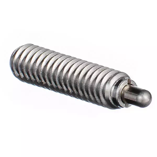
| Stainless Steel | Good in corrosive environments food processing and high temperature applications (spring can withstand 600°F) Grades: 440C***, 300 Series per ASTM A-484 or ASTM A-582, 17-PH | B,P,L,S |
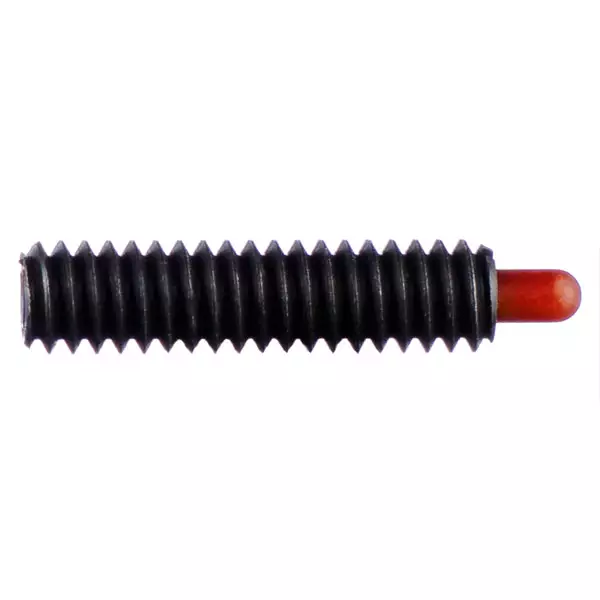
| Carbon Steel | Less expensive material than stainless steel and better wear resistance of the plunger tip due to case hardening.** Grades: 11L17 or 12L14A or Ledloy AX | B,P |
| Music Wire | Used on most carbon steel products. | S |
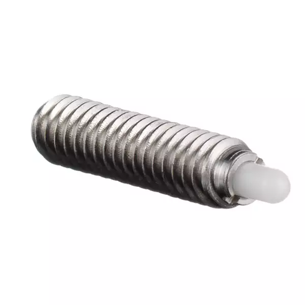
| Nylon or Delrin® | Will not mar soft material such as aluminum or brass. | B,P,L |
| Phenolic | Will not mar soft material such as aluminum or brass. More brittle than nylon or Delrin. | B,P |
Delrin® is a registered trademark of DuPont Corp.
*(B) Body • (P) Plunger • (L) Ball • (S) Spring
**NOTE: All steel plungers are typically case hardened to 0.15-.010 inches in depth to a hardness of between RC 58-62.
Finish Platings
- Zinc plate; yellow, clear or black chromate to conversion coat
- Black oxide
- Passivate; SAE-AMS-QQ-P-35, ASTM-A-967***
- Other special coatings
Body Alloy Material Specifications
| Material Grade | Tensile PSI | Yield PSI | Elong.* | Hardness** |
| 440C | 110,000 | 65,000 | 14 | Br230 |
| 302,304,304L | 65,000 | 35,000 | 80 | Br150 |
| 303S | 100,000 | 60,000 | 40 | Br228 |
| 316,316L | 80,000 | 35,000 | 55 | Br149 |
| 321,347 | 85,000 | 35,000 | 55 | Br150 |
| 12L14 | 80,000 | 60,000 | 10 | Rc B85 |
| LEDLOY AX | 80,000 | 60,000 | 10 | Rc B85 |
| 11L17 | 80,000 | 60,000 | 10 | Rc B85 |
* Elongation 2°, %
** Br = Brinell, Rc = Rockwell
*** Stainless steel components are passivated prior to assembly
Spring Material Specifications
| Material Grade | Max Temp°F | Max Temp°C | Hardness* |
| Music Wire | 250 | 121 | Rc C41-60 |
| 17-7PH | 650 | 343 | Rc C38-57 |
* Rc = Rockwell
Plastic Material Specifications
| Material Description | Service Temperature°F | Tensile(1) | Ln. Exp.(2) | Hardness* |
| Delrin** | 195 | 9,000 | 5 | Rc M80-90 |
| Nylon | 180 | 12,000 | 4.5 | Rc R120 |
| Phenolic | 284 | 20,000 | - | Rm 110 |
(1) Yield Strength, PSI
(2) Linear Thermal Expansion IN/IN F°10(-5)
* Rc = Rockwell, Br = Brinell
** Acetal (Celcon, Delrin)

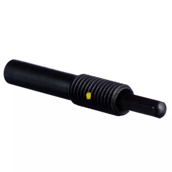
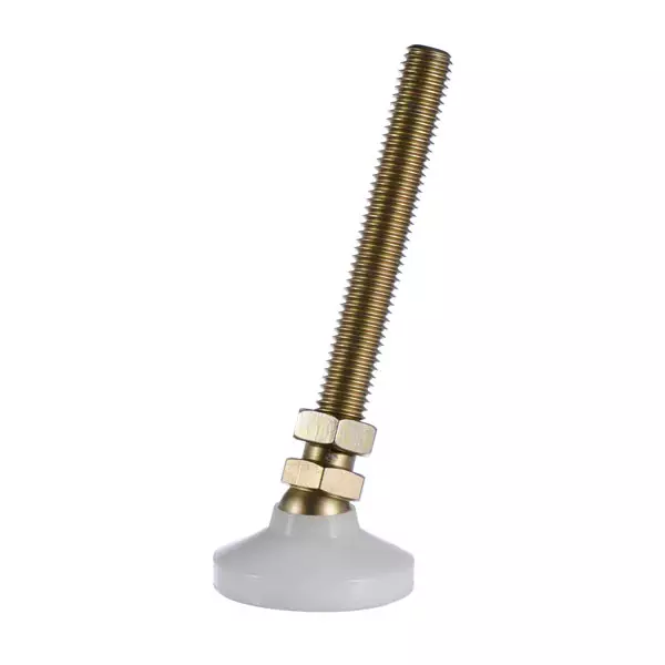
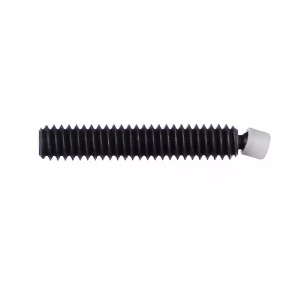
How to Order the With Thread Lock Element
When ordering the locking element, add a “P” to the end of the part number for threaded enhanced springs.
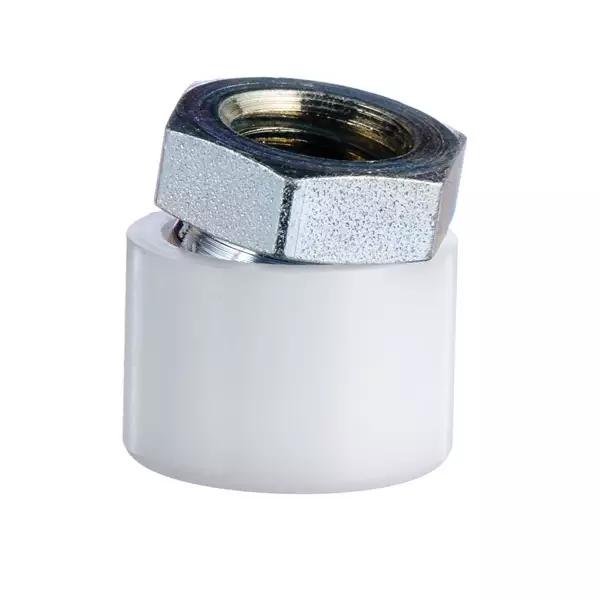
Installation With With Thread Lock Elements
When using the pellet-type locking element (thread sizes 1/4 inch and larger), we strongly recommend that you countersink the mating thread 90 degrees by 1/32” larger than the major thread diameter. This prevents the nylon pellet, which is press-fit into the body of the spring loaded device, from dislodging.
How the With Thread Lock Element Works
The nylon locking element provides the thread locking property by forcing the threads on the opposite side of an SLD to compress against the mating threads of a tapped hole. This compression action can sometimes cause problems when installing into soft metals. The steel threads of a spring plunger can cause damage when they are forced against the softer aluminum threads of a tapped hole, impeding installation or removal.
Vlier’s Lighter With Thread Lock Element
Compared to years past, we now employ a much lighter locking element, and our spring plungers work in soft metal applications the vast majority of the time. If our standard locking element doesn’t install in your application easily, you can try using a larger drill in the tapping operation, or contact technical support for a quote on a custom part.
Properly designed detents used with spring loaded devices (SLDs) ensure engagement and disengagement of mating parts at a predetermined position and force. Improperly designed detents can cause excessive wear on nylon or Delrin® Nose plunger tips, which can decrease positioning accuracy and adversely affect SLD holding capacity. As a general rule, the smaller the contact angle of the detent, the easier the SLD will kick out of it, and the longer the plunger tip will last.

Maximum Spring Loaded Device Installation Torques
The maximum installation torques SLDs can withstand are significantly less than bolts or screws. Use the table and additional information provided below as a guide for installing Vlier SLDs. If you need more specific information, please contact technical support.
Installation Torques for SLD's
| Unified Thread Size | Metric Thread Size | Max Installation Torque (Inch Pounds) |
| No. 4 | M2.5x0.45 | 0.6 |
| No. 5 | M3.5x0.5 | 1.25 |
| No. 6 | M3.5x0.6-6g | 1.65 |
| No. 8 | M4x0.7-6g | 2.15 |
| No. 10 | M5x0.8-6g | 3.15 |
| 1/4 | M6x1-6g | 6 |
| 5/16 | M8x1.25 | 11 |
| 3/8 | M10x1.5 | 16 |
| 7/16 | M11x1.5 | 22 |
| 1/2 | M12x1.75 | 28 |
| 9/16 | M14x2.0 | 36 |
| 5/8 | M16x2.0 | 55 |
| 3/4 | M20x2.5 | 70 |
| 7/8 | M22x2.5 | 95 |
| 1 | M24x3.0 | 130 |
| 1-1/8 | M30x3.5 | 160 |
| 1-1/4 | M33x3.5 | 190 |
Installation Into Different Materials
Installation problems can occur when an SLD supplied with a nylon locking element is installed into soft metals and locking helicoils. Aluminum threads may be damaged by the steel threads of the SLD during installation, making it difficult for deeper installation or removal. When installing only a few SLDs into soft metals, we recommend that you purchase them without the nylon locking element, and use a thread locking adhesive or helicoil. When installing large quantities of SLDs, it may be cost-effective to ask Vlier to apply a lighter nylon locking element or apply the nylon locking element in a different location on the body.
Installing Into Helicoils
With Thread Lock helicoils can cause the same installation problems as the nylon locking element. We recommend never using the nylon locking element when also using a locking helicoil. Regular helicoils may be used in conjunction with the nylon locking element, but Vlier recommends that you may still want to prototype the installation or discuss it with Vlier technical support. When using locking helicoils, Vlier suggests that you experiment with different drill sizes during the tapping operation, and determine which drill size or thread class supplies the appropriate amount of thread locking while still requiring minimum installation effort.
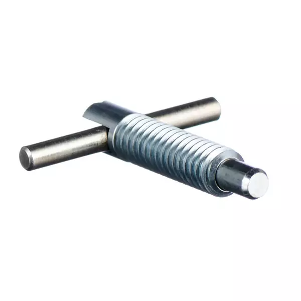
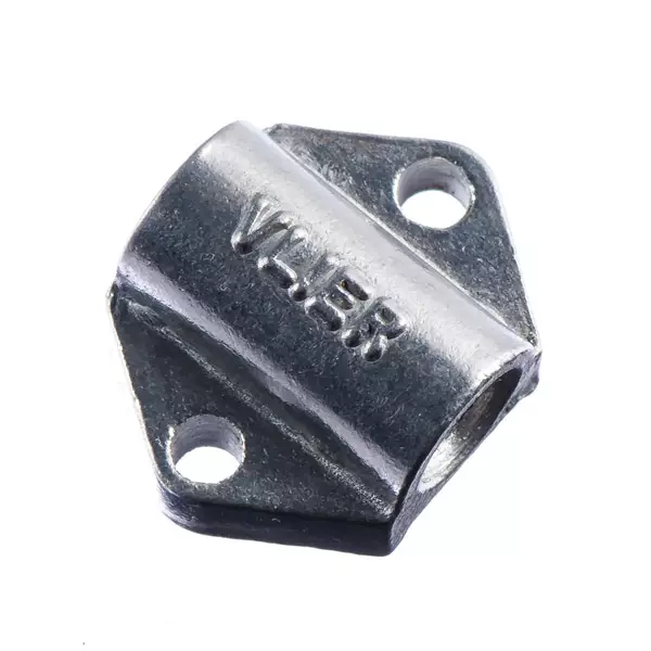
Using the Vlier Wrench
You can use the Vlier wrench when installing an SLD from the front end of the body, but because of its design, the wrench can break if the recommended installation torques are exceeded.
Blind Hole Applications
The bottom few threads of a blind hole are often imperfect threads and can cause difficulty when installing SLDs. Vlier recommends that blind holes be tapped using bottom taps or tapped deeper than necessary, where possible.
Using Power Screwdrivers
When set on the lowest torque level, power screwdrivers can provide more constant pressure on the slot than can be obtained by using a regular screwdriver. This may allow SLDs to be installed in tight threads that may not have been otherwise possible.